Elements of a wireless network
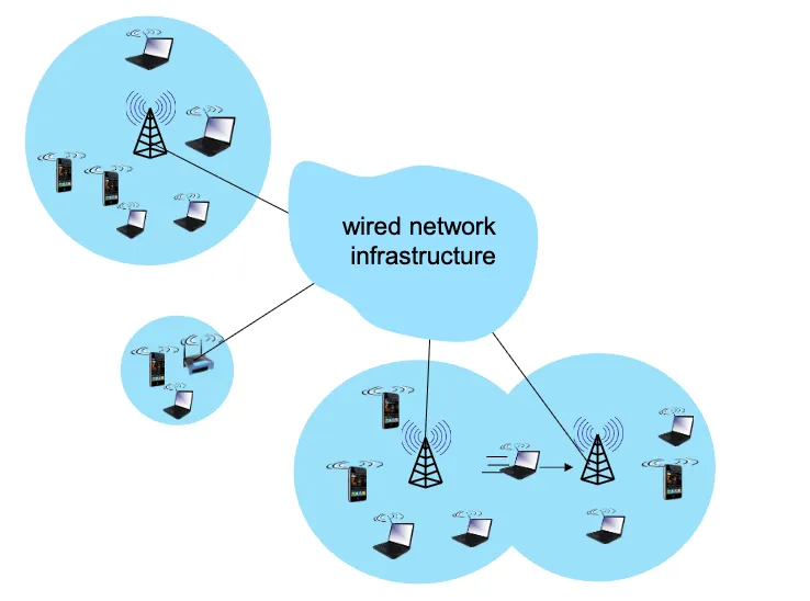
- Wireless Hosts:
- Devices that have built-in wireless network interfaces; run applications.
- Examples: laptops, smartphones, tablets
- Base Stations (BS):
- Responsible for sending packets between wired networks and wireless hosts within a certain geographical area.
- Specialized access points that connect wireless hosts to the wired network.
- Examples: cellular base stations, WiFi access points.
- Wireless Links:
- Connect wireless hosts to base stations. Multiple access protocol coordinates link access.
- Various transmission rates, distances, and frequency bands.
Note
Wireless does not mean mobile! A desktop computer can have a wireless interface, but it is not mobile.
Infrastructure vs. Ad-Hoc Mode
Infrastructure Mode: In infrastructure mode, a wireless network operates with a central device called an access point (AP) that manages all communication between wireless hosts and often connects them to a wired backbone such as the Internet. In this setup, devices do not communicate directly with each other; instead, every packet is first sent to the AP, which then relays it to the intended destination. This mode provides centralized management, easier authentication and security control, greater scalability, and the ability to integrate wireless devices with existing wired networks.
- Infrastructure mode uses a central access point, like a router, to connect devices, enabling integration with wired networks and faster speeds.
- Base stations connect wireless hosts to the wired network.
- Handoff: mobile changes base stations while communicating.
Ad-Hoc Mode: In ad hoc mode, wireless devices communicate directly with one another without the use of an access point. This makes the network quick and simple to set up, useful for temporary or small peer-to-peer connections. However, ad hoc mode lacks centralized management, is generally less secure, and does not provide direct connectivity to wired networks or the Internet. As a result, while infrastructure mode is preferred for most real-world deployments due to its stability and integration, ad hoc mode is better suited for short-lived, localized communication.
- Allows direct peer-to-peer communication between devices without a central point, creating a simple, temporary, and decentralized network but with limited security and integration capabilities.
- No base stations, hosts communicate directly.
- Node can only transmit to other nodes within link coverage.
- Nodes organize themselves into a network; route among themselves.
Wireless Network Taxonomy
| Single Hop | Multi Hop | |
|---|---|---|
| Infrastructure | hosts connect to base station (which connects to larger internet) | hosts may have to relay through several wireless nodes to connect to larger internet (e.g., mesh network) |
| No Infrastructure | no base station, no connection to larger internet (e.g., Bluetooth) | no base station, no connection to larger internet. May have to relay through several wireless nodes (e.g., MANET) |
Wireless Links
Characteristics of Wireless Links
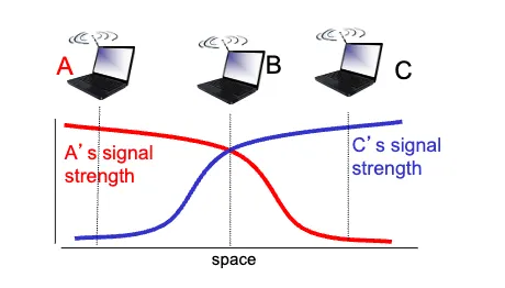
- Signal Attenuation:
- Signal strength decreases with distance.
- Path loss: Reduction in power density of electromagnetic wave as it propagates through space/medium.
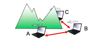
- B, A hear each other
- B, C hear each other
- A, C cannot hear each other because of B’s interference
- Interference from other sources:
- Other devices transmitting in the same frequency band.
- Multi-path propagation:
- Signals take multiple paths to reach the receiver.
- Ex: radio signals reflecting off buildings/ground, arriving at slightly different times.
- Hidden terminal problem:
- Suppose node A wants to send to B.
- Another node C also wants to send to B, but A and C are out of range of each other.
- Because A and C can’t hear each other, they can both try to send to B at the same time.
- From B’s perspective, that’s a collision.
- SNR (Signal to Noise Ratio):
- Ratio of signal power to noise power.
- Higher SNR = better quality link (easier to extract signal from noise).
Note (SNR vs. BER (Bit Error Rate))
Wireless links are more error-prone than wired links due to signal attenuation, interference, multi-path propagation, and hidden terminal problem.
- Physical layer: increase power ⟶ increase SNR ⟶ decrease BER
- SNR: choose physical layer that meets BER requirement with highest throughput
- It may change with mobility; dynamically adapt physical layer
- modulation technique, rate, etc.
⟶ Wireless communication is much more difficult than wired communication
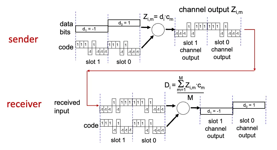
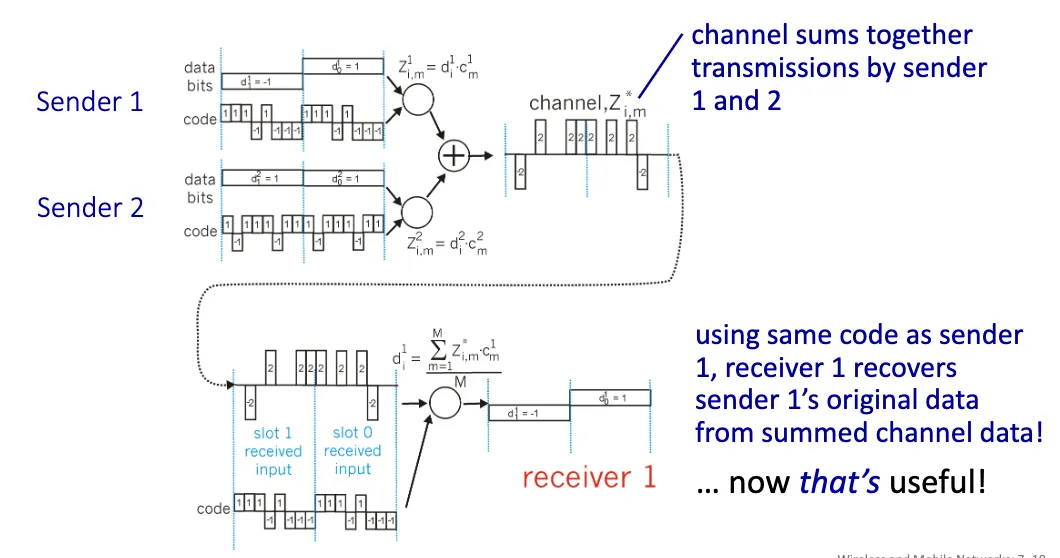
Code Division Multiple Access (CDMA)
Code Division Multiple Access (CDMA) is a channel access method used by various radio communication technologies. It allows multiple users to share the same frequency band simultaneously by assigning unique code sequences to each user. CDMA is widely used in cellular networks, satellite communications, and other wireless systems.
Definition (Modulation)
- The exertion of a modifying or controlling influence on something.
- In telecommunications, modulation is the process of varying a carrier signal in order to transmit data
Code Set Partitioning:
- A unique code sequence is assigned to each sender, and all users share the same frequency band.
- Each user has their own “chipping” sequence to encode their signal.
- Allows multiple users to transmit simultaneously without interfering with each other (if codes are orthogonal).
- Receiver uses the same code sequence to demodulate the signal.
Advantages
- Efficient spectrum usage: All users share the same frequency band, so it can support more users than TDMA/FDMA.
- Resistance to interference: Spreading codes make signals look like noise to others, improving robustness against narrowband interference.
- Security: Data is harder to intercept without knowing the unique code.
- Soft handoff in cellular systems: Calls can seamlessly move between base stations.
- Multipath resistance: Spreading/despreading helps mitigate fading caused by signal reflections.
Disadvantages
- Near-far problem: Strong signals can drown out weaker ones unless strict power control is enforced.
- Complexity: Requires sophisticated synchronization, code management, and decoding.
- Limited code space: Only so many orthogonal/semi-orthogonal codes can be assigned before interference grows.
- Capacity limit: More users increase background noise, degrading overall system performance.
- Latency: Spread spectrum processing can add overhead compared to simpler schemes.
Wireless LANS
Wireless LANs are local area networks (LANs) that use wireless links. All use CSMA/CA (Carrier Sense Multiple Access with Collision Avoidance), and have base station & ad-hoc network versions.
Architecture
- Wireless host communicates with base station (access point)
- Basic Service Set (BSS):
- Set of wireless hosts communicating with each other
- Wireless hosts, Access Point (AP, aka. base station), ad-hoc mode (hosts only)
Channels, Association
- Spectrum divided into channels at different frequencies
- Access point (AP) admin chooses frequency for AP
- Interference happens when channel is the same as that chosen by nearby AP
- Arriving host must associate with an AP
- AP periodically broadcasts beacon frames containing AP’s Name (SSID) and MAC address
- Selects an AP to associate with based on signal strength of beacon frames
- May perform authentication
- Typically runs DHCP (Dynamic Host Configuration Protocol) to get IP address in AP’s subnet
Passive vs. Active Scanning
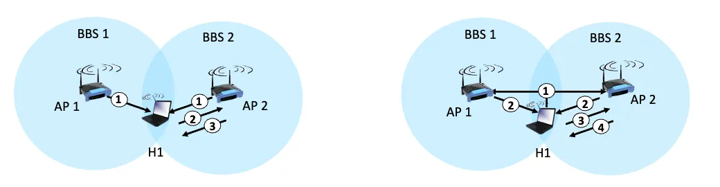
| Passive Scanning | Active Scanning |
|---|---|
| 1. Beacon frames sent periodically by AP | 1. H1 sends probe request frame |
| 2. Association request frame sent; H1 to AP | 2. Probe response frame sent from APs |
| 3. Association response frame sent; AP to H1 | 3. Association request frame sent; H1 to AP |
| 4. Association response frame sent; AP to H1 |
802.11: Wireless LANs
802.11 is a set of standards for wireless LANs (WLANs) developed by the IEEE. It is the most widely used wireless LAN standard and operates in unlicensed frequency bands, making it accessible for various applications.
Definition (Definitions for 802.11)
- DCF: Distributed Coordination Function
- Ad-hoc mode
- PCF: Point Coordination Function
- Infrastructure mode
- DIFS: DCF (Distributed Inter-Frame Space)
- SIFS: Short Inter-Frame Space
- Slot time: time to transmit 1,500 byte frame
- 9 - 50 microseconds, depending on physical layer
Multiple Access in IEEE 802.11
nodes transmitting at the same time ⟶ collision
So how do we avoid collisions?
CSMA/CA (Carrier Sense Multiple Access with Collision Avoidance)
This is a network protocol that listens to a network in order to avoid collisions. The basic idea is to sense the channel before transmitting, and if the channel is busy, wait before trying again.
However, sensing before transmitting is not easy because:
- High transmitting signal drowns out weak received signal due to fading.
- Hidden terminal problem.
IEEE 802.11 MAC Protocol
802.11 sender
- If channel idle for DIFS (Distributed Inter-Frame Space), transmit entire frame (no collision detection)
- If channel busy
- Start random back off time, wait until idle, then wait DIFS, then transmit with probability
- If collision (no ACK received), double back off window, choose new random back off time, go to step 2-1.
802.11 receiver
- If frame received OK, wait SIFS (Short Inter-Frame Space), then send ACK.
Note (Why ACK?)
- Ack is needed due to hidden terminal problem.
- If A sends to B successfully, but C also transmitted and interfered, A has no way of knowing if B actually got the frame. Since A can’t sense C directly, carrier sensing alone can’t solve it.
- If no ACK, sender assumes collision.
More on avoiding collisions
To further reduce collisions, 802.11 uses RTS/CTS (Request to Send / Clear to Send) mechanism.
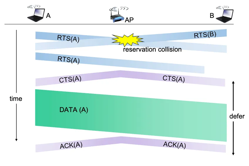
- Sender “reserves” channel before sending data
- Sender sends RTS (Request to Send) frame to BS using CSMA.
- RTS may still collide with other RTS frames, but RTS frames are short so less likely to collide.
- BS broadcasts CTS (Clear to Send) frame as a response.
- CTS is heard by all nodes.
- Sender transmits data frame after receiving CTS.
- Other nodes hearing RTS or CTS defer their transmissions.
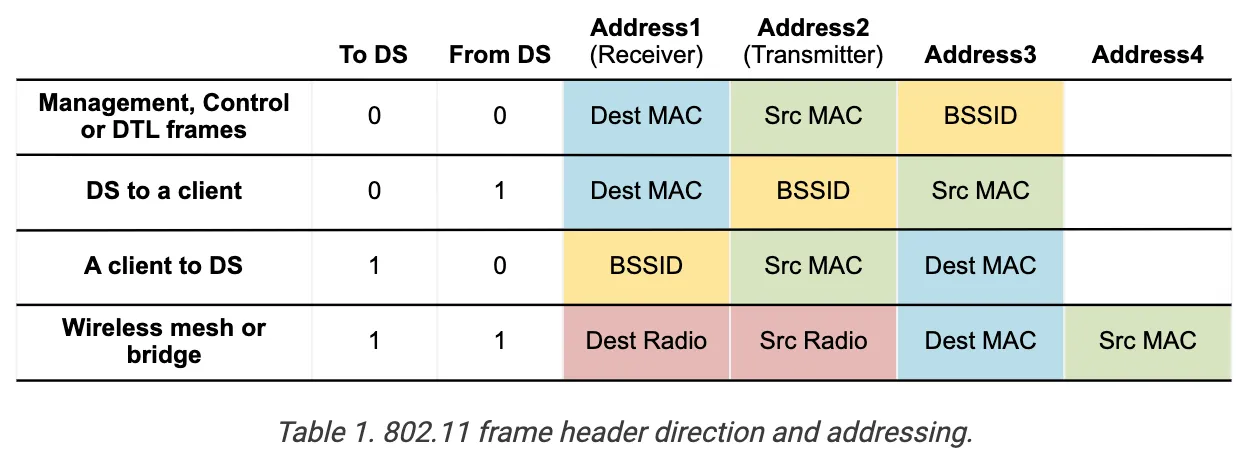
802.11 Frame Structure
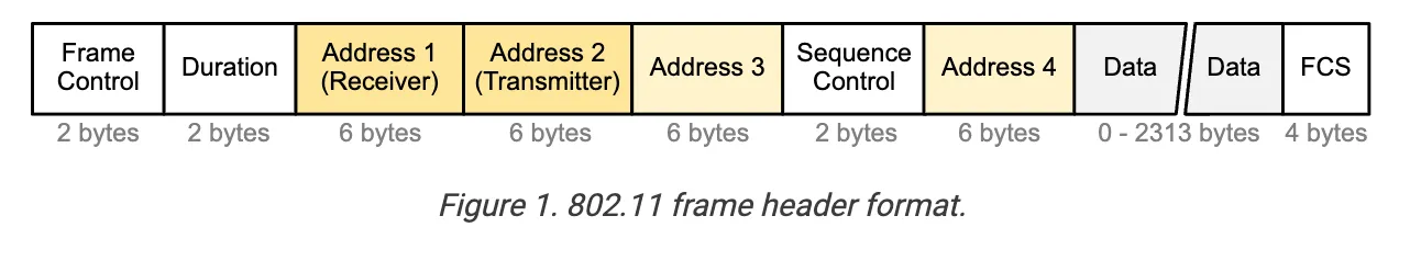
- Frame Control: Protocol version, type, and other control information (RTS, CTS, ACK, data, etc.).
- Duration: Time (in microseconds) the channel will be reserved for this frame (RTS/CTS).
- Sequence Control: Frame sequencing for fragmentation/reassembly.
- Also used for reliable data transfer.
- Address 1: Holds the MAC address of the receiver (AP or wireless host).
- Receiver Address (RA).
- Address 2: Holds the MAC address of the transmitter (AP or wireless host).
- Transmitter Address (TA).
- Address 3: Holds the MAC address of the router to which AP is connected.
- Destination Address (DA).
- Address 4: Only used in an ad-hoc network.
- only used when one AP is forwarding to another AP over a wireless link.
- carries the original Source Address (SA) and Destination Address (DA).
- Address 1 & 2 remain the RA and TA for the APs relaying the frame.
Note (Why 3 Addresses?)
Address 3 contains the real ethernet-level MAC that exists beyond the immediate wireless link. Without Address 3, the AP and the client wouldn’t know how to bridge traffic between wireless and wired worlds.
In other words, Addr1 and Addr2 are hop-to-hop addresses (intermediate), while Addr3 is the end-to-end address (final).
So while transmitting, Addr1 and Addr2 change at every hop, but Addr3 remains the same end-to-end.
802.11 Advanced Capabilities
Rate Adaptation
- Base station, mobile nodes can dynamically change transmission rate as mobile moves and SNR changes.
- If SNR decreases, BER increases as node moves away from base station.
- If BER becomes too high, switch to lower transmission rate but with lower BER.
Power Management
Radio States: Instant hardware states of the transceiver
- Awake: Able to receive and transmit frames.
- Doze (sleep): Transceiver off, cannot receive or transmit frames; Low power consumption.
Client States: Long-term policy of the client device
- Active mode: transceiver always on
- Power-save mode
- transceiver off periodically
- AP buffers eligible frames for this node while it is asleep
Note (Power-Save Mode)
A client in PS mode is not always in Doze state. It switches between Awake and Doze states periodically.
If your phone is in power-save mode, it will turn on its transceiver (Awake state) periodically to check for buffered frames at the AP, and then go back to Doze state.
Personal area Networks (PANs): Bluetooth
- Short-range (10m) communication between devices
- Ad-hoc network; no infrastructure
- Master-slave architecture, where master controls medium access
- parked mode:
- clients can be parked (inactive) to save power
- bootstrapping:
- nodes self-assemble into piconets
- piconet is a star topology with master at center